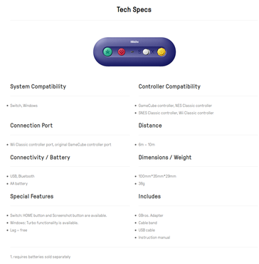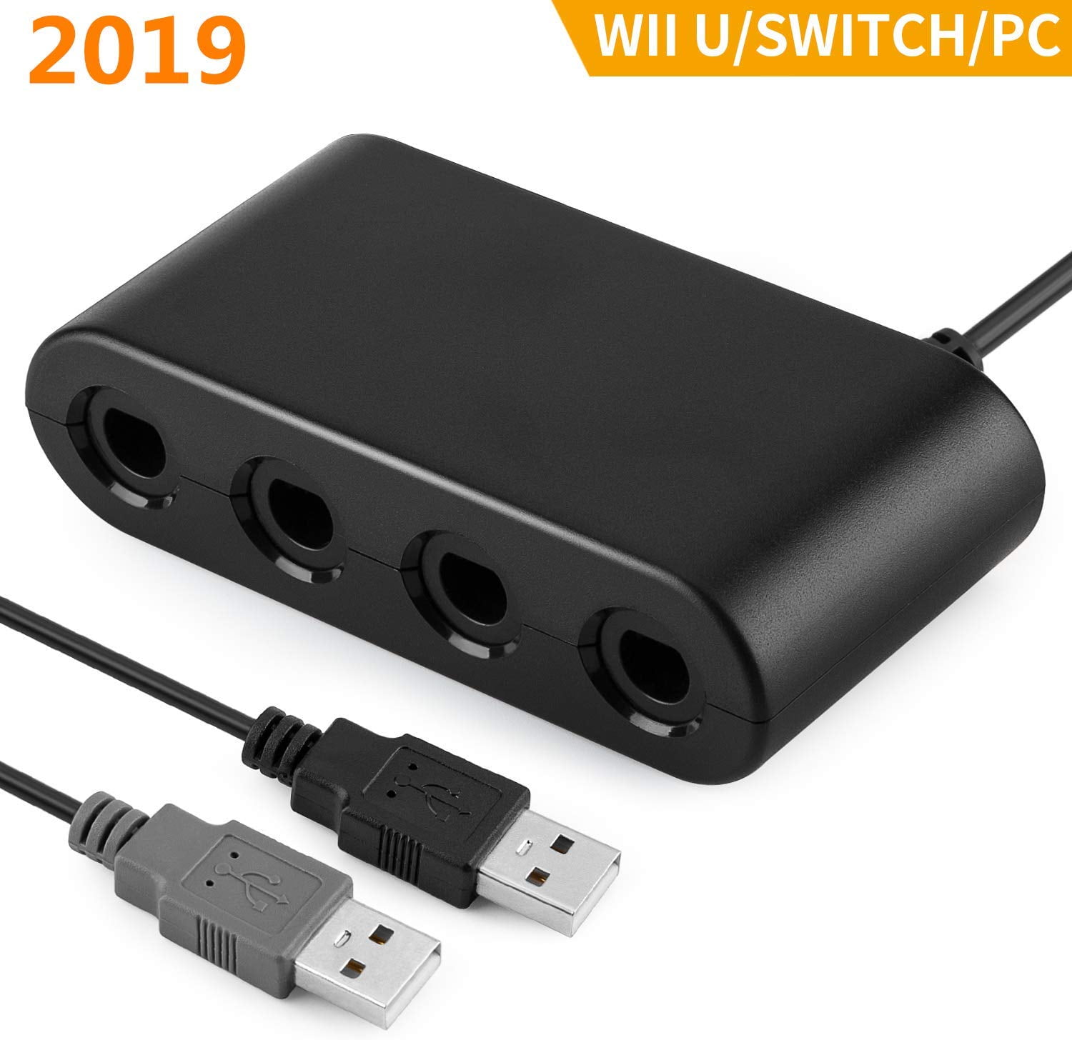

- SWITCH GAMECUBE USB ADAPTER UPDATE
- SWITCH GAMECUBE USB ADAPTER DRIVER
- SWITCH GAMECUBE USB ADAPTER PC
- SWITCH GAMECUBE USB ADAPTER WINDOWS

This is due to the HORI communication timing being very different from original Nintento pads.

SWITCH GAMECUBE USB ADAPTER UPDATE
Update gamecube reception code using the new N64 algorithm from 1.3.It's the same wire protocol so it makes sense. N64/Gamecube communication code is now shared between the N64 and GC drivers.New asm transmission code capable of sending many bytes with perfect timing.See calibration_fixer/readme.txt for details.
SWITCH GAMECUBE USB ADAPTER WINDOWS
SWITCH GAMECUBE USB ADAPTER DRIVER
Implemented using standard HID PID (Physical Interface Device) which means: No special driver required.N64 rumble pack and Gamecube controller built-in vibration supported!.Changed the device name to allow easier version identification.Controller swapping still worked fine though. Fixed USB detection when no controllers are present.The calibration fixer source code is now included.Calibration fixer updated to support this new firmware.(Better responsiveness in games such as Super Smash Bros) Reduced USB interrupt-in poll interval.Simplified main loop by removing setIdle/getIdle implementation, optional for joysticks according to HID specification appendix G.(Should also work with Atmega88 and 328 ) Used to switch from Joystick to Keyboard mode. Rework for device/report descriptor switching.Add support for the Gamecube ASCII keyboard.The adapter now enumerate without controllers as it used to. Fix non-working timeout when waiting for the controller.Helps some cheap 3rd party controllers that have the Left not working problem. Blindly following color codes without any checks can be a good way to ruin electronics. Keep in mind that wire colors varies between manufactures, and sometimes between revisions of the same product. Gamecube connector to the PCB inside the receiver seem to be I have been informed that the color of the wires running from the Note: The picture comes from motorola's lm317 datasheet: lm317rev1g.pdf Any voltage between 3.26 and 3.40 volts should do the job. If you use an lm317 variable voltage regulator, here's a simple tool which can help youįind a good value for R1. In order to obtain 3.3 volts, you can use a fixed voltage regulator such as the 78M33C orĪn adjustable voltage regulator such as the lm317 or lm1117 ( exemple). I measuredģ.36 volts on my N64 so personally, I choose to supply 3.3 volts to my Gamecube Said that the Nintendo 64 supplies 5 volts to the controllers (Wrong!). I readĪn old message in the -consoles news group where the author Some other pages says it's any voltage between 3.3 and 3.8! volts. Some webpages mention that the Gamecube controllers work at 3.43 volts,

For this reason, a voltage regulator is required.Īpart from the different firmware, this is the only difference (and additional complexity) Gamecube and Nintendo 64 controllers both work at 3.3 volts. Use a very similar protocol, it was easy to support Gamecube controllers so I developped an adapter for doing this.
SWITCH GAMECUBE USB ADAPTER PC
One of my friends wanted to play Nintendo 64 games on his PC using an originalĬontroller.


 0 kommentar(er)
